1) What are the forms of internal separation (Form Factors) defined in IEC 61439?
Before trying to understand the forms of separation, it is essential to understand the symbols & technical terms used to define it.
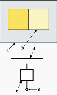
- Enclosure
- Internal separation
- Functional unit
- Busbars, including distribution busbars
- Terminal(s) for external conductors
Useful Definitions to Understand the Form of Segregation (Source IEC 61439-1)
Assembly - Combination of one or more low-voltage switching devices together with associated control, measuring, signaling, protective, regulating equipment, with all the internal electrical and mechanical interconnections and structural parts
Functional Unit - part of an ASSEMBLY comprising all the electrical and mechanical elements including switching devices that contribute to the fulfillment of the same function
Busbar - Low-impedance conductor to which several electric circuits can be separately connected
Main busbar - Busbar to which one or several distribution busbars and/or incoming and outgoing units can be connected
Distribution busbar - Busbar within one section which is connected to a main busbar and from which outgoing units are supplied
Enclosure - Housing affording the type and degree of protection suitable for the intended application
As per IEC 61439-2 Annex AA, following are the internal separations to be used in low voltage switchgear & control gear assemblies. (Source IEC 61439-2)
FORM 1
No Internal Separation
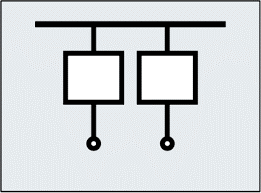
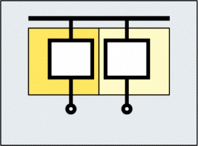
FORM 2
Separation of busbars from all functional units
Form 2a:
Terminals not separated from busbars
Form 2b:
Terminals separated from busbars
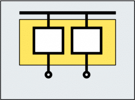
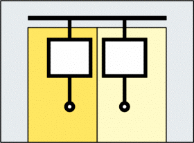
FORM 3
Separation of busbars from all functional units
+
Separation of all functional units from one another
+
Separation of terminals for external conductors and external conductors from the functional units, but not from the terminals of other functional units
Form 3a:
Terminals not separated from busbars
Form 3b:
Terminals and external conductors separated from busbars
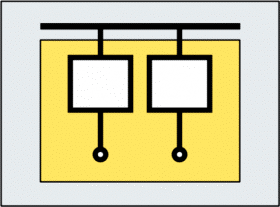
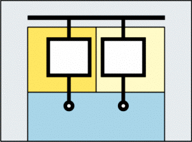
FORM 4
Separation of busbars from all functional units
+
Separation of all functional units from one another
+
Separation of terminals for external conductors associated with a functional unit from the terminals of any other functional unit and the busbars
+
Separation of the external conductors from the busbars
+
Separation of the external conductors associated with a functional unit from other functional units and their terminals
+
External conductors need not be separated from each other
Form 4a:
Terminals in same compartment as associated functional unit
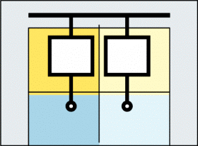
Form 4b:
Terminals not in same compartment as associated functional unit
2) Who is the original manufacturer & who is the assembly manufacturer as per IEC 61439? Are they different parties or the same party? Does it complies with the standard IEC 61439 if an assembly Manufacturer assembles panels complying to original manufacturer’s design?
Original manufacturer is the organization that has carried out the original design and the associated verification of an ASSEMBLY in accordance with the relevant ASSEMBLY standard (IEC 61439-1 clause 3.10.1)
Assembly manufacturer is the organization taking the responsibility for the completed ASSEMBLY (IEC 61439-1 clause 3.10.2)
Assembly manufacturer & the original manufacturer need not to be the same party as per IEC 61439-1. It is 100% complies with IEC 61439 standard if assembly manufacturer assembles panels complying with original manufacturers design. After completing the assembly, assembly manufacturer shall carry out routine verification defined in IEC 61439 clause 11 to verify the assembly is up to standards.
Verification shall comprise the following categories:
- Construction:
- Degree of protection of enclosures;
- Clearances and creepage distances;
- Protection against electric shock and integrity of protective circuits;
- Incorporation of built-in components;
- Internal electrical circuits and connections;
- Terminals for external conductors;
- Mechanical operation.
- Performance:
- Dielectric properties;
- Wiring, operational performance and function.
3) What are the types of Surge Protection Devices (SPDs) & what are the protections provided by those.
Before identifying SPD types, it is necessary to have an understanding on the types of surges which are originated on an LV electrical installation and Lightning protection zones.
- Lightning current that is caused by direct lightning or partial discharge current characterized by 10/350µs pulse and
- Induced surge current with a typical waveform 8/20 µs.
Depending on the exposure to Lightning Electro-Magnetic Pulse (LEMP) a building can be divided into 3 main zones IEC 62305-4).
- LPZ-0: Zone where threat exists due to full or partial lightning current (generally outside a building)
- LPZ-1: Immediate internal zone of a building. Surge current is limited by current sharing, isolating surface and/or SPD at the boundary of LPZ-0 and LPZ-1
- LPZ- 2: Surge current is further reduced by current distribution, isolating surface and/or SPDs at the boundary.
As per IEC 61643-11/2011, there are three types of SPDs.
- Type 1 SPD
- Type 2 SPD
- Type 3 SPD
The Type 1 SPD is recommended in the specific case of service-sector and industrial buildings, protected by a lightning protection system or a meshed cage. It protects electrical installations against lightning impulse currents generated due to direct lightning strokes. It can discharge the back-current from lightning spreading from the earth conductor to the network conductors. Type 1 SPD is characterized by a 10/350 μs current wave.
The Type 2 SPD is the main protection system for all low voltage electrical installations. Installed in each electrical switchboard, it prevents the spread of over voltages in the electrical installations and protects the loads. Type 2 SPD is characterized by an 8/20 μs current wave.
These SPDs have a low discharge capacity. They must therefore mandatorily be installed as a supplement to Type 2 SPD and in the vicinity of sensitive loads. Type 3 SPD is characterized by a combination of voltage waves (1.2/50 μs) and current waves (8/20 μs).
(Source- Electrical Installation Guide by Schneider Electric)
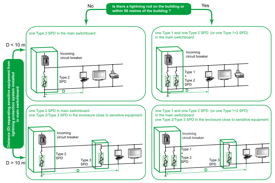
4) How to decide the type of Surge Protection Device & where it needs to be installed in order to provide the protection to the electrical installation of a building.
Selection of SPD type & location is very important for the protection of electrical installation of a building. Following figure shows the logic behind the selection & placement of SPDs. Please note the conditions stated in the picture in providing SPDs.
Preventive maintenance does help to increase the life time not only for the panel boards, but also for almost all the equipment/devices. Depending in the weather condition (high or low ambient temperature, humid conditions, etc), location (indoor, outdoor, near to sea, dusty, etc), surroundings (such as vibrating equipment nearby, etc) & application, frequency for preventive maintenance may be varied. However, preventive maintenance of panel boards helps to reduce down times & early identification of possible failures while making panel boards safer & reliable to your building. Prevention is always better than cure.
5) Does preventive maintenance required for electrical panel boards?
Yes indeed. Normally a panel board is dispatched out from a factory after carrying out a set of predefined tests (as per standards or ISO procedure). Therefore someone might think it is not essential to carry out a pre inspection before energizing a panel. However, it is not a very intelligent decision due to various reasons such as;
- If test reports are available with the panel board, you know for sure that the panel board is subjected to verification tests before leaving the factory (it is a standard practice). But if the test reports are not available with you & if a non-standard manufacturer has manufactured the panel board, it is better to make sure that the panel board is healthy for energizing.
- In the transportation of panel board from factory to the final destination, there might be some cases of loosening of wires, as delivery process is not always under supervision of a skilled (electrical related) personnel.
It is necessary to carry out pre inspections especially for tightness of all electrical connections, connections of incoming breaker, phase sequence of the terminals of the incoming breaker & insulation test between all phases.
6) What are the general colors & RAL numbers of powder coated enclosures?
Most of the times, RAL 7032 (Pebble Grey) & RAL-7035 (Light Grey) are used for power panels. However, for special applications such as Fire DBs, Capacitor Banks and etc, different colors such as Light Orange may be used depending on the customer’s requirement & his organizational standards.

